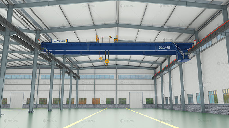
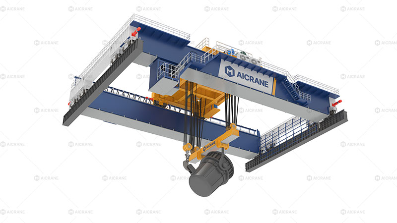
Designing a trolley and hoist mechanism for a 100-ton overhead crane is a highly complex engineering task that requires precise calculations, careful selection of components, and adherence to safety and performance standards. The trolley and hoist are the heart of the crane’s lifting system, directly determining the crane’s load handling efficiency, safety, and service life. When dealing with a load capacity as high as 100 tons, the design process becomes even more critical, as the margin for error is minimal.
This article explores the key design considerations for trolley and hoist mechanisms in a 100 ton overhead crane, covering structural design, drive systems, load distribution, safety measures, and maintenance requirements.

1. Understanding the Load Requirements
Before diving into the detailed design, engineers must fully understand the lifting requirements:
-
Maximum load: 100 tons (including hook, rigging, and any lifting accessories).
-
Load type: Whether it is evenly distributed, concentrated, or dynamic (e.g., molten metal in foundries).
-
Duty classification: According to FEM or ISO standards, a high-capacity double girder crane often falls under heavy-duty classes (e.g., FEM 3m–4m or ISO M7–M8).
-
Operating environment: Temperature, humidity, dust, corrosive atmosphere, or explosive conditions will affect the choice of materials and protection measures.
This early-stage information guides not only the trolley and hoist size but also motor ratings, gearbox design, and safety factor calculations.
2. Trolley Frame and Structural Design
The trolley frame must be robust enough to carry the hoist mechanism, gearboxes, drive motors, and the lifted load without deformation.
Key considerations:
-
Material selection: High-strength structural steel with excellent fatigue resistance, typically S355 or higher grades, is preferred.
-
Welded box construction vs. open frame:
-
Box construction offers higher rigidity and better resistance to torsional stress.
-
Open frame may be lighter and easier to maintain but can be less stiff.
-
-
Deflection limits: Excessive deflection can misalign the hoist drum or wire rope, causing uneven load distribution.
-
Wheelbase and load distribution: The trolley wheels must be positioned to evenly distribute the weight across the bridge girders, minimizing stress concentration.
3. Hoist Mechanism Design
The hoist mechanism is responsible for the vertical lifting motion and must be designed for both strength and precision.
3.1 Hoist Drum and Wire Rope
-
Drum diameter: Large enough to reduce wire rope bending stress. Typically, the drum diameter should be at least 20–24 times the rope diameter.
-
Rope selection: High-strength steel wire ropes with anti-rotation construction are recommended. The rope’s breaking strength must be at least 5–7 times the working load.
-
Grooving: Spiral or Lebus grooving ensures even rope winding and reduces wear.
3.2 Hook and Hook Block
-
Hook design: Forged steel hooks conforming to DIN or ISO standards. For 100 tons, a double hook arrangement may be considered to improve load stability.
-
Swiveling: Hooks should swivel 360° under load for operational flexibility.
-
Sheave arrangement: The number and size of sheaves determine the mechanical advantage and influence the rope reeving system.
3.3 Gearbox and Motor
-
Motor type: High-torque squirrel-cage or wound rotor motors with variable frequency drives (VFD) for smooth acceleration and deceleration.
-
Gearbox design: Hardened and ground gears to handle high torque and reduce noise. The gearbox must be capable of withstanding shock loads without failure.

4. Trolley Travel Mechanism
The trolley travel mechanism moves the hoist across the crane bridge. For a 100-ton crane, the design must ensure smooth and controlled travel under full load.
Key design factors:
-
Wheel material: Forged steel wheels with surface hardening for wear resistance.
-
Wheel alignment: Misalignment increases rail wear and power consumption.
-
Drive system: Independent drives for each side or a common drive with a shaft connection. Dual-motor drives with synchronized control are common for high-capacity trolleys.
-
Speed control: VFDs are preferred to minimize load swing and improve positioning accuracy.
-
Bearing selection: Heavy-duty roller bearings with adequate sealing to prevent dust ingress.
5. Load Distribution and Stability
For a 100-ton crane, the trolley must be designed to handle uneven loading conditions without tipping or overloading one side.
-
Center of gravity (CG): The CG must be kept low and within the wheelbase for stability.
-
Multiple wheel assemblies: Instead of four wheels, some trolleys use eight wheels to distribute the load more evenly.
-
Structural reinforcements: Additional gussets and stiffeners prevent distortion under skew loads.
6. Safety Devices and Redundancy
Safety is non-negotiable in high-capacity bridge crane design. The trolley and hoist mechanisms should integrate multiple safety measures.
Common devices include:
-
Overload limiters: Load cells or strain gauge sensors to prevent lifting above rated capacity.
-
Upper and lower limit switches: Prevent the hook from overwinding or bottoming out.
-
Emergency brakes: High-capacity disc or drum brakes that can hold the load securely in case of power loss.
-
Rope failure protection: Rope guards and slack rope detectors.
-
Anti-collision sensors: For trolleys operating on the same bridge.
7. Vibration and Noise Control
High-capacity trolleys can produce significant vibration and noise during operation, which can lead to fatigue failures and discomfort for operators.
-
Shock absorption: Use of resilient wheel mounts and buffers.
-
Precision machining: Ensures proper gear meshing and reduces noise.
-
Dynamic balancing: For drums, sheaves, and rotating parts to prevent excessive vibration.
8. Maintenance Accessibility
A 100-ton trolley and hoist are large and complex, so ease of maintenance should be considered from the start.
-
Walkways and service platforms: Allow safe access for inspection and repair.
-
Modular components: Gearboxes, motors, and brake systems should be removable without dismantling the entire trolley.
-
Lubrication systems: Centralized or automatic lubrication ensures consistent maintenance.
9. Environmental Adaptations
If the crane operates in special environments, additional design steps are needed:
-
Marine/coastal areas: Anti-corrosion coatings and stainless steel components.
-
High temperatures: Heat-resistant insulation and cooling systems.
-
Cold climates: Low-temperature lubricants and heaters for motors and gearboxes.
-
Dusty environments: Sealed bearings and motors with high ingress protection (IP) ratings.
10. Compliance with Standards
The design must comply with international standards such as:
-
FEM (Federation Europeenne de la Manutention)
-
ISO (International Organization for Standardization)
-
CMAA (Crane Manufacturers Association of America)
-
EN and DIN standards for mechanical components.
Following these guidelines ensures global acceptance, safety, and reliability.
Conclusion
The trolley and hoist mechanism for a 100-ton overhead crane is a critical subsystem that must be designed with precision, safety, and durability in mind. From the choice of materials and structural configuration to motor drives, safety devices, and maintenance features, every detail influences the crane’s performance and service life. A well-designed system not only handles the heavy loads reliably but also ensures operator safety, minimizes downtime, and offers long-term cost savings.
When working with such high-capacity equipment, partnering with an experienced eot crane manufacturer and adhering to recognized standards is essential. The engineering investment in a robust trolley and hoist design pays off through improved efficiency, reduced maintenance costs, and enhanced operational safety.
